
I placed the cover on the gasket sheet and drew around with a marker. Then I marked the holes and cut them with a wad punch. Cutting the inner paper away was more awkward but care and attention paid off. Finally the outer paper was trimmed off. It seems like a lot of trouble to make a gasket when they are just a few dollars however alternatively matching and making correct size spacers is as much work if not more.

The timing cover had chrome build up on a copper base. It was very thick and uneven on the gasket surface so needed machining flat and true. Chrome can be such a menace at times. Also the two dowel holes were thick with chrome making the cover tight to remove so I used a reamer to correct size the holes. During assembly I was careful not allow Loctite 515 sealer to coat the dowels as it locks the cover tightly making removal even more difficult.

The timing gears were covered in light rust possibly from when it ran US gasoline with the alcohol content. I've seen similar effects on competition alcohol engines. The thought is, alcohol attracts water which in turn rusts.
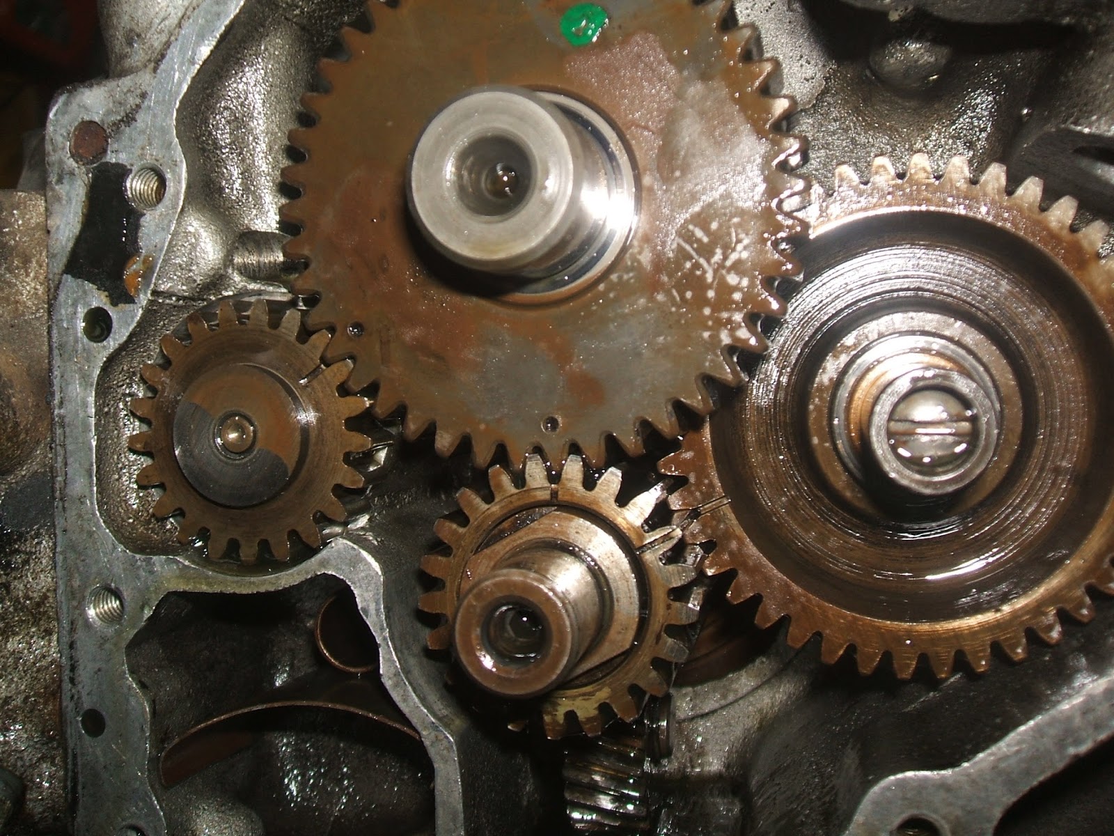
Top: FLH cam is marked with "H" on a lobe. Left: breather. Right: distributor-timer drive gear. Bottom: crank pinion gear.

Lower left is part of the breather system. There should be a gauze to help remove foam/bubbles from the oil but was missing.

Breather screen made from stainless perforated sheet.


Tappet/hydraulic lifter screen pieces. The screen had a tear so was solder repaired.


I rounded up a selection of springs to use the best one for the job. Should the strainer plug, the spring would compress allowing oil to bypass. The spring I settled on was from a ballpoint pen.

The screen got an extra washer soldered to it's flange so making it a better fit in its' housing.


Oil pump assembly with re-zinc plated studs, nuts, plugs, etc. The oil switch pictured had seen better days. The center bakelite part was loose so I tried to tighten the crimp but it sulked and was replaced with a temporary one which switches at 10psi. The switching pressure is a little high meaning the oil light comes on at idle too easily. I think one that switches at a low single digit figure would suffice.
Thanks for viewing. I hope you found this interesting.
It´s great bike., I have a panhead chopper -65, With andrews j cam, it´s much smoother ride. Have a problem with the charge, the generator armature, stopped charging three times. Now I have changed three times. Do not know the error. Run with volt pack.
ReplyDeleteHave a nice ride in the wind.
Kungsor Sweden.