
It turned out in quite good condition, quite clear but with some sediment.

The allen head drain screw is a tapered thread fit so I applied Loctite 567 teflon paste. I use this product a lot for all sorts, but especially as thread sealant. One manual stated 190cc of 30 weight oil and the closest I had was 20/50.
Update: Bike rides quite well with the fork oil changed as above, partly because the amount that came out was noticeably less than 190cc.
I made tools to use on wheel nuts. They're fashioned from old allen head cap screws which are very tough steel, probably chromoly.
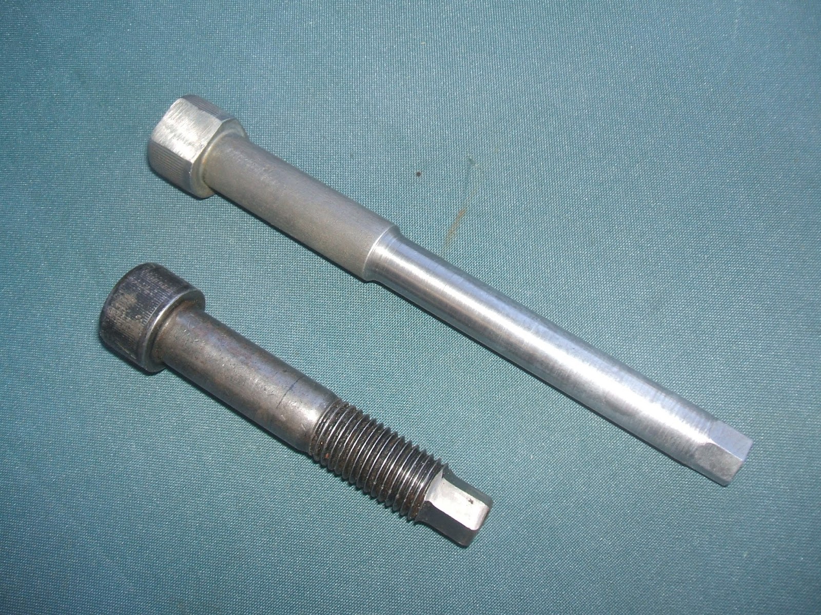
They're difficult to shape nicely and get the hex accurate. The upper one will be carried in the tool box. Two opposing "flats" were ground into the head so it uses a regular spanner to turn it.

7April2016
I started work on the rear brakes. The shoes were excellent condition and not even bed in. The wheel cylinder honed up perfect so I'll buy new cup seals for it from a brake shop.
The brake drum is cracked so am studying various options.


Crack runs through lug nut hole. Also a dowel is broken off.

The sprocket is a bit worn, maybe just usable. The o-ring chain was well worn out plus the joiner wasn't the correct match, had O-rings missing and was seized.
Video of drum-to-hub dowel wear. Clearance 1mm (.040"):
12April When wheel lug bolts are loose, the drive power will pull/rotate the drum in one direction. Brake effort pulls it the other way. Easy to see why most of the wear is on the "torque side" of the 5 holes! The more this wears the more it loosens and the more it loosens, the more it wears. Quite the vicious cycle. At this moment I'm proposing to build up the holes with weld and carefully whittle them to a nice fit. Probably I'll de-lace the rim and those spokes needed re-plating anyway!
18April2016 I welded the dowel holes, putting a small patch at the site of the wear. I carefully worked the holes with a file till it fitted well. It took maybe an hour. Because 4 dowels are used and 1 is new the hub only fits in just 1 of the 5 possible orientations. So I'm marking it so it can be assembled always this way. That is, until I replace the drum. Then it will have 5 new dowels and I'll relieve the dowel holes again for a perfect fit.

21April2016 Re-zinc-plated spokes and nipples laced, trued and centered. Loctite nickel antiseize was used on the spoke threads. Hub is painted with White Knight Rust Guard Epoxy Enamel.
Pic shows wheel in the wheel building jig..

27April2016 The re-lacing was completed and the wheel got trued and balanced with a new white wall tire.


Front brake and wheel
I removed the front wheel to find a few surprises. The anchor bolt was bent.


This is the anchor point for the brake plate and shoes. It was bent and cracked.

Cracks here too. The plate had a serious shunt at some time in the past.

Cracks as seen from the outside of cover

Wheel nut lugs plated with zinc in my DIY bath. I discovered the secret to getting an improved, shiny zinc finish is to emery polish the steel back to bright.

Hub painted with epoxy black.

Re-lacing of the wheel using a donor (safety bead) rim and spokes, both in tidy condition. A wheel truing jig made the work easier.

The spokes were tuned. Rim aligned to 1 7/8" spec according to Palmers HD book.
Update: the rim turned out to be incorrect fitment for a star hub because spokes clash on the right side. It was a 90's Sportster rim. I reverted back to the original Pan rim.
Update: the rim turned out to be incorrect fitment for a star hub because spokes clash on the right side. It was a 90's Sportster rim. I reverted back to the original Pan rim.

The drum had been chromed at some stage in the distant past. I painted the area as shown to cover rust.

I found one brake shoe lining was pulled way on one end. A little wiggle and it popped right off!! YIKES!!

It doesn't look like the bond was ever keyed on properly.

As can be seen, the linings were yet to bed in, so have done very little work. Now I understand why the brake was improving with use. The brake work was done a long time ago, not recently.

The glue can be seen inside the shoe looking bubbly and maybe the result of the heat process during bonding.

New linings bonded to the original shoes. They are soft lining type..
I roughed up the cast iron drum friction surface with coarse emery cloth.

With heat from a LPG torch, this tool is how I removed the bearing cover insert..

Insert size was different so I turned it on a lathe. Here assembled ready..

All set. The brakes will take some time to bed in

21Aug2106 The new brake shoes did not bed in as expected and the brake lever had a spongy feel. I decided to investigate. I found the shoe pivots were not true to the shoe and hence were not correctly position against the drum. Pic shows an engineers square against a 5/8" piece of steel shaft sitting in the pivot. It is quite a few degrees out of true.

Both shoes sit on the same 5/8" shaft. One is worse than the other.

Am considering repair options such as TIG weld/ re-drill the pivot. The plan is to submerge the lining in water with only the weld area protruding. This will prevent overheating of the bonded lining.

The situation was worse than first thought. The shoes needed reworking because effectively the cam lever was too far from the theoretical ideal of 90°. 1st pic shows cam in retracted position but look at the pivot end!!

Lever engaging shoes has moved too far so past the point of maximum leverage.

Flash pic of the cam taking up the clearance only...

It needs about 5 -6mm adjustment/ rework.
Currently I'm studying upgrading the brake from pinned to sliding type aka floating shoe.
Floating shoe (experimental modification)
30Aug2016 Firstly I made a spindle from chromoly steel solid round bar.
It's threaded 7/16". This will be the abutment for the shoes to slide against.

Then I made a sleeve and split it into two halves.

The shoes were carefully trimmed to length and for exact fit then tack welded (to the sleeve halves)

The two sleeves were stitch welded to the shoes taking care not to overheat the lining.

Next is contouring the contact area of the shoe to fit the 14mm abutment. It has about 3mm 1/8" sliding freeplay.

17sep2016 Testing this mod shortly...
Wheel Tracking/Alignment
Swingarm
16Sep2016 I discovered the swingarm was bent. The tire was too close to the inner fender on the LH side.
Here is my "quick & dirty" method of checking straightness. A 3/4" shaft is fitted through the pivot bearings. A small amount of preload is achieved with 2 hoseclips, 2 washers and 2 springs as pictured.

Sighting along the 2 shafts it could determined one leg was 1/8" 3mm higher.

Swingarm pivot pin thread had seen better days.

De-rust and zinc plating to freshen it up. Tide mark of plating bath clearly visible.

Method used to straighten swingarm. Note the lever/bar across the two legs (coming in from lower right). Take care, they move very easily. I chose to re-check for true several times throughout the process. At first, the legs were visibly flexing, then I progressively increased the force till I got the required accuracy.
The red paint is to aid sighting across the two alignment bars. It makes the second bar easier to see because of the contrast in color. Hoping to confirm the work by placing on a table saw top which is a convenient flat and true surface. I'd need to make V-blocks, etc to suit.

The seals are an unusual size for a seal. They measure the same as the bearings do at 1 25/32" (1.781"). The Seal shop turned me away saying I'd need a genuine part or adapt. Later I visited their website and found the correct seals there, they had 7 in stock all along!
No doubt about the bearing needing replacement. These are very common, found on trailer axles etc.
Cup & cone: LM11910 & LM11949

Front wheel aligning
I used inside-calipers to check front wheel was central between fork legs. The rim had been previously trued within spec for run-out. I took multiple readings between rim and adjacent fork leg, rotating the wheel ¼ turn each time. I averaged the readings.

Fork Aligning
I made a special tool to check fork alignment.


Using this tool and a straight edge against the upper stanchions, I'm able to achieve good alignment accuracy.
Straight edge used to sight by eye down to the special tool.

Front Rim respoke rework
Finally I realized I had to get rid of the 90's Sportster rim I'd fitted to the front because the spokes clashed on the RHS, It's due to the way the rim holes are drilled (incorrect hole pattern).
Refitting the original (rusty) rim was straightforward. All the spokes were much happier.

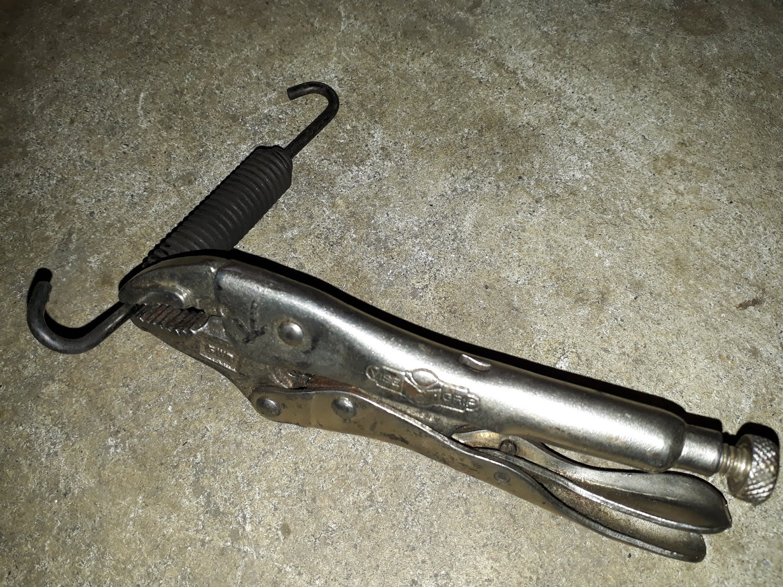
This is the method I use to fit brake shoe springs. The vice grip is a small variety perhaps 6" long. I grip spring at exactly the optimum place and angle so it can be stretched into position. Same for spring removal.
Important: Springs assembled in the notches furthest from the drum, otherwise springs rub on the drum!

Method of clamping the cable for maximum strength..

I elected to do the truing with wheel fitted in forks so I made this jig to achieve it. It's adjustable for both "out-of-round" and "run out". It worked quite satisfactorily for a simple impromptu tool made on the spot. Also exactly centralization of rim between fork legs was set by comparing caliper measurement to fork legs.

4Feb2018 I renewed the rear shocks with Progressive suspension complete units. These have progressive wound springs and multi-stage velocity sensitive damping.
This is how the RH shock came off...

The spear had unscrewed internally.

The dome fitted, though the shock casing was 1/8" bigger. Centers are 13.5".
Spring rate is satisfactory for one-up riding.

The ride is good. It soaks up the bumps like never before. Recommended upgrade.
Sag amounts to 14mm from a maximum travel of 51mm. Spring tension is on the lightest setting.
Rear Brakes and sprocket
20/7/2019

Old rear Bendix shoes with cracks in lining. I believe the lining material hardens with age, then rider applies more pedal force to achieve the same power. Result is heat stress cracking. While these are very old shoes they hadn't even fully bed into the drum.

New bonded Ferodo linings onto the existing Bendix shoes.

5mm x 16mm cap screws with nylock nuts replaced the failing rivets which had worked loose.

Tiny nylock nuts are small enough to have clearance to the drum.
Fork suspension upgrade (RaceTech)
7/19

Stanchion cap small oil holes were plugged with a piece of nail linished to light interference fit and Loctite 243. The Allen head cap screws will be inserted from above to facilitate future oil changes. An O-ring is used to seal the thread into the stanchion (pictured).

Damper rods were modified. Extra/bigger holes at the bottom and a 2mm rebound hole.

Racetech "cartridge emulators". I used the blue/black springs with 3 turns preload.

Parts of the upgrade. New springs to suit.

Machined rebound damper components

Brass valve is 2-way, adjustable rebound. Compression damping is set by oil weight.

Damper rod is drilled with extra/bigger holes.

Also the damper rod has an additional 2mm rebound hole.

Extra non stock items are steel or aluminum 6061/7075

Damper rods were smoothed and polished to remedy existing scoring.

Spring is shorter but heavier than stock. PVC tube will be used to set preload.

Rebound valve stack, one part is original.

Mock assembly of the unit

Brass valve is set to 3 turns spring preload as per recommended starting point.

View of extra/bigger holes.

Stanchion cap was counterbored to suit allen head cap screw to allow oil changes.

James seal kit. Discarded now in favor of low friction seals. See below...

The pieces. Vesconite (piston ring material) 3mm wide x 2.5mm thick.

45° taper cut to accommodate o-ring

During assembly
First road was encouraging. The suspension felt firm yet accommodated bumps well.
4Jan2020
I completed adjustment of the High Speed damper valve preload spring. I reduced it 3/4 turn then a further 1/2 turn. The effect was awesome. The "hydraulic lock" effect has been dramatically reduced on big, hard edge bumps. Very happy with the improvement. Road testing for some weeks before final evaluation.
29Aug2020
Latest set up:
5w oil
Lightest valve spring on lightest setting.
Simple wire hook tool for removing valve..

11April2021
Problems continued so I stripped the forks and inspected. One damper rod was bent and both uppers ends were not brazed on true from factory. The damper rods were also getting scored on existing parts of the damper valving. I increased clearances and polished the rods. Upper end of the rods were lathe trued and groomed so the adaptor could benefit from certain amount of self alignment.
Latest setup
10w oil
20mm preload
.90kg springs
Lightest valve spring on lightest setting
Oil level with spring installed 28mm above valve.
Fork behavior is the best it has been. Much of the previous problem was due to sticktion.
19Sep2021
Fitted a rubber pad to brake pedal. The rubber was very hard so I dremelled it out and glued it. Earlier I'd pushed one on and it split overnight.. One minor unexpected problem is the reduced foot clearance to the shaker board. Plan is to snick a bit off the underside with a disc sander.

Rear brake adjusting hack. I use a 3/8" drive extension as pictured. Saves risk of rounding off the square because it can be tight.


Low friction seals are good. It's a difference you can feel. Very pleased.

Swingarm. New pin made from chromoly 4140 steel.. A spacer was machined to set bearing preload. Works well.


No comments:
Post a Comment