Wednesday, December 9, 2015

Timing marks, distributor-timer, log book.

I checked my timing marks on the bikes' flywheel. I used a degree wheel to accurately determine TDC. Then I moved the flywheel to the 35° point on the degree wheel (full advance).
I drew pictures of the marks for reference. They were perhaps a degree out compared to factory pictures..
Log book for record keeping.

Timings marks as they appear in the timing window. True TDC and 35° marks.
Note: I punched a small dot on the case to eliminate guesswork. I recommend cleaning the timing marks with thinners, then painting with white marker pen or white paint and artist brush. I also carefully marked the rear cylinder, using black and white paint to highlight it. Strobe timing showed how poor the timer condition really was.

A special tool made to service the timer rear base bolt.. It needed heating with oxy/acetylene torch till red hot, then bending to the appropriate shape.

The bikes' timer had been severely hacked and modified to take an auto advance mechanism. As I write, I'm waiting on a single point replacement to arrive from Canada.

These pics are my old timer.

The body has been brazed and does not dismantle like stock ones.

It had a later automatic advance weight set up

It couldn't be removed without head removal else I have to cut it. It fouls the heads' fins as it lifts out.

The replacement timer arrived before the Xmas rush. It looked good. I replaced the screw that holds the points for a longer one so I could use a spring and flat washer. I fitted another condenser. It strobed well with the marks much more stable. With the front cyl dash perfectly on the mark, the rear cylinder was slightly retarded. I tickled a tiny mount off the lrading edge of the more advanced cam lobe. I was surprised how little needed to be removed to make a difference!
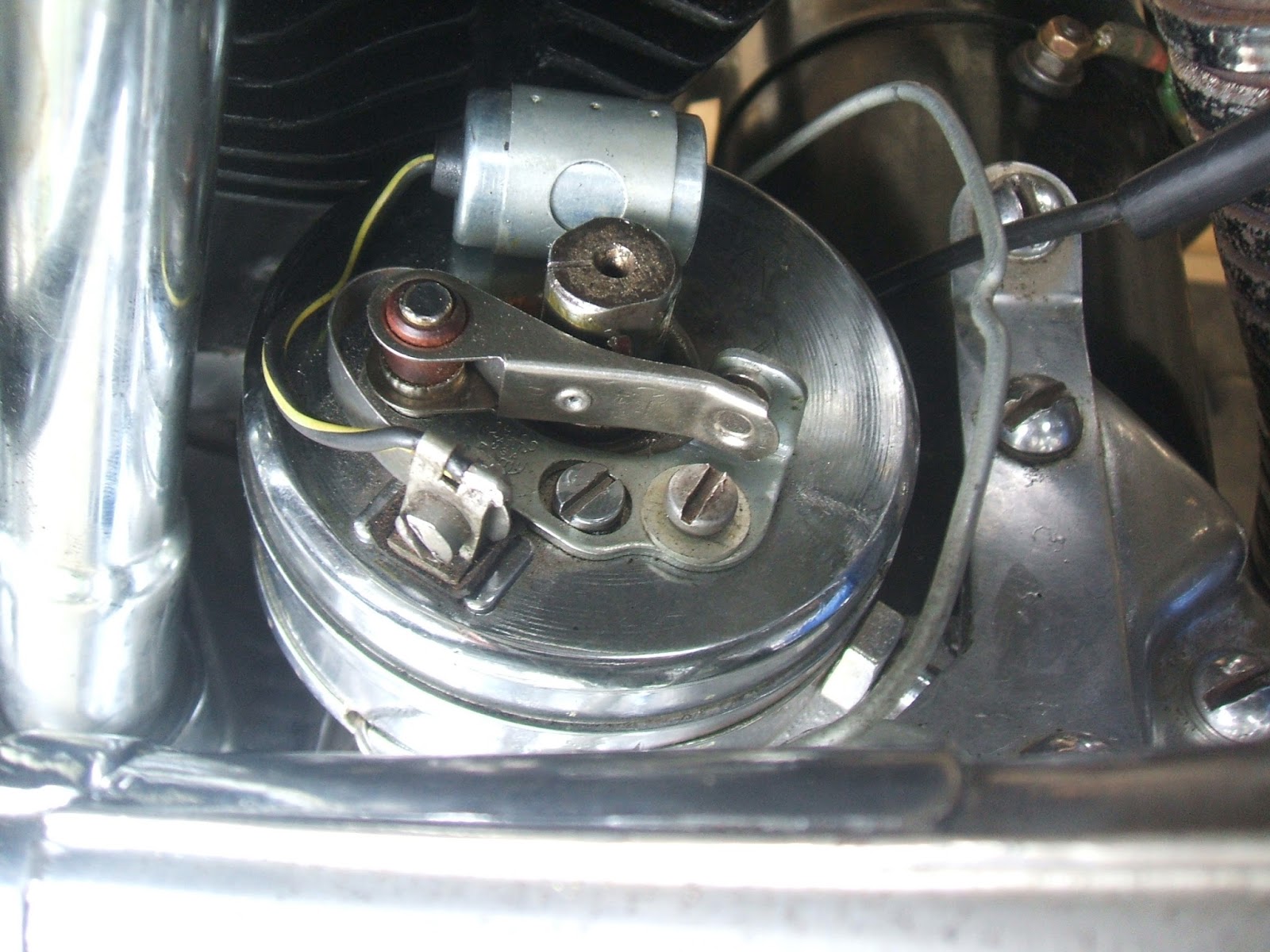
This pic shows a cheap repop condenser. I've since changed it for the old Delco condenser the timer came with. This gives less visible sparking at the points with early indications of better running and easier starting as well. Testing shortly...
Update: A problem remains, especially starting


6V Dyna coil

23Jan. No sooner said when another problem emerged. The engine was giving an occasional misfire, then it got progressively worse. I headed home. I began checking voltages. I discovered the ignition wire to the coil had .5 volts more when the switch was in "lights" position. I realigned the switch on the base and carefully cleaned up the hole in the dash console. It was applying pressure to the switch possibly causing havoc with the contacts. Testing next opportunity, perhaps tomorrow..

My ignition switch was losing one volt through the switch so I soldered the contacts to their tabs. The crazing is actually electrical spray grease by Wurth. It came out pretty good so I'm proceeding to reassemble and test..

Ultimately I fitted a relay to bridge battery to coil directly. This eliminates voltage drop at switch, etc.

Re-bushing the timer

18 Dec 2019 The time came to repair the slop in the timer shaft and bushes. I bought sintered bronze bushes that were a bigger OD and smaller ID so I could turn them to exact dimensions.
Studying sintered bronze showed the bushes aren't supposed to be honed though reaming is OK if the reamer is very sharp. Machine finishing is ideal. Blunt tooling smears the sintered porous holes closed so best avoided.

Theory: The porous bush material holds oil so as the bush heats up, oil gets released for lubrication. This seems ideal in situations where oil feed is non-existant or erratic. There are a few caveats..

The shaft was polished between lathe centers using emery cloth on a flat file. The unworn part of the journal was half a thou bigger  so this was carefully reduced. Fine wet & dry paper was used to get a nice finish. The shaft was rust pitted but I didn't attempt to remove it all. When the timer housing was chrome plated decades ago, the shaft was not removed so this may explain the rust pits.


I turned the bush OD to half a thou interference then pressed them in with a draw bolt made from thread stock. I used no Loctite because I didn't want it impregnating the sintered bush.

I centered the timer in the 4jaw and sized it till the shaft fitted nicely. The lower bush wasn't fitted yet so the shaft could be check-fitted at the top bush alone. Next I pulled the lower bush into place. Then I centered the timer from the other end. A steady was used to hold it in position. Finally the bush was sized and timer removed from the 4jaw. This was the moment of truth. Would the shaft slide right through, meaning that the 2 bushes were perfectly aligned. Yes, success!

The fitted bushes now need oil impregnating. I heated a small container of motor oil and let the timer sit in it, then cool. I cycled it a few times, end for end, hot and cold while immersed. The hot and cold are said to draw oil into the pores. (Do not use grease)


Thursday, December 3, 2015

Cyinder head, bolts, valves

The original heads were cracked and some valve seat wear.
 There was some existing repairs. The threads and fins were good.

 New reproduction cylinder heads manufactured by STD developments were purchased. New Black Diamond valves and guides were fitted. The seats were cut and valve lapped in.
There was a tiny pin hole in the casting leading to the oil drilling that fed the rockers. Oil leaked profusely (at mains pressure). Arrow indicates hole.. (Click on pic to blow up).
The repair was made using 3/16" brass tube from a model/hobby shop. I bought a 12" length chosen from a large selection of tube, rod etc. The drilling from the head gasket face was first cleaned up with a 3/16" reamer then carefully cleaned with acetone. Loctite 620 was used because of its' high heat rating. The chart said resistant to 230°C (446°F). Overnight cure before testing to 30 psi. Despite the close proximity to the combustion chamber, 230°C Loctite sounded reasonable especially when considering the oil flow would help draw heat away.

Panheads have 5 head bolts per head/barrel. Some of my bolts had yielded so I elected to upgrade to Shovelhead type which supercedes them by part# 16814-77.  Pictured is Shovel type to left. OEM Pan type to right..
I zinc plated these bolts as part of my refurbishment.

I bought 2 NOS bolts. The packet was crumbling but the bolts were perfect. Pan washers were used to achieve correct length.

New STD Development heads were fitted and these bolts were checked for length. Instructions warn than the bolt under the intake can break through into the port. Mine were clear by 3mm/1/8".

I used locally available valve guide seals with Teflon wiper. They were too long so I trimmed the bottom, losing the circlip and groove. I used hi-temp RTV to glue them in place after thorough degreasing with acetone.
The pan cover screws were not cut deep enough by the maker (STD). They are 10-24 UNC, same TPI as BSW. I hunted and hunted for a 10-24. I did not have one amongst the hundred or so taps I own.  A friend had one in a large set. I borrowed it but while it was brand new/never used, it would not cut the thread! I was as though the tap was blunt and simply slipping over the surface. The further I screwed it in, the tighter it got. The tap was marked "carbon steel", not the preferred HSS (high speed steel). The head material is very hard and difficult to work. I gave up and returned the tap. I had a BSW 3/16" HSS tap and I pondered over whether it would do the job. Especially I didn't want the screws to be a loose, floppy fit in the thread. I drilled and tapped in scrap aluminum and was happy with the result so I proceeded to deepen all pan cover screws holes. The BSW HSS tap was up to the task and the screws fitted nicely.


I made an adaptor to fit a 3/8" drive socket set to tighten and torque the bolts.


Thanks for viewing.

Tuesday, December 1, 2015

Zinc plating nuts bolts and brackets DIY at home


 Some of the items plated, ready for assembly


Three Barrel studs ready, compared to an unplated one. Only the ends were visible on assembly but worth the effort.

Pic taken during assembly. Barrel nuts were parkerized replica items.
 
The electrolyte came from Caswell plating way back in the 90's but should a replacement be needed I'm going to try a DIY formula. Vinegar, Epsom salts and sugar. Zinc strip is available as a roof maintenance aid also from marine/boat shops and scrap metal dealers.
 
Please see side page for more details. (top right) Thanks

Intake manifold

Pan intake manifold Tees are somewhat crude in design. Air leaks at the seals are fairly common. To combat the problem, leak testers are used with about 12 -15psi pressure. Soapy water is lathered over the seal area, carb gasket stack and adjacent area including known leak points like rocker cover screws, etc. A continuous stream of bubbles is a fail and needs addressing for proper engine behavior and health. Take care to wash the soapy residue away after testing as it rusts/corrodes some metals.
Snoop leak detection liquid is said to give superior results over soap and is available from Swagelok.

My DIY leak tester made to suit Linkert flange manifold.

A simple adjustable air regulator, gauge, push-lok fittings and air coupler

Monday, November 30, 2015

Linkert carburetor

The Linkert M74B carb post has been moved to its' own page.
See top right below page view counter

Sunday, November 29, 2015

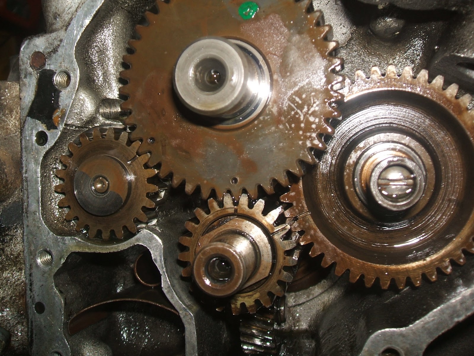
Inside the timing cover, oil pump.

I made a new gasket from .015" gasket paper. The object is to get the end play of the gears within specification. The gear driving the dizzy timer is particularly critical. Now I need only remove .001" from its' spacer to achieve minimum clearance of .003". Getting this gear correct will mean the ignition timing will be more stable.
 
I placed the cover on the gasket sheet and drew around with a marker. Then I marked the holes and cut them with a wad punch. Cutting the inner paper away was more awkward but care and attention paid off. Finally the outer paper was trimmed off. It seems like a lot of trouble to make a gasket when they are just a few dollars however alternatively matching and making correct size spacers is as much work if not more.

The timing cover had chrome build up on a copper base. It was very thick and uneven on the gasket surface so needed machining flat and true. Chrome can be such a menace at times. Also the two dowel holes were thick with chrome making the cover tight to remove so I used a reamer to correct size the holes. During assembly I was careful not allow Loctite 515 sealer to coat the dowels as it locks the cover tightly making removal even more difficult.
 
The timing gears were covered in light rust possibly from when it ran US gasoline with the alcohol content. I've seen similar effects on competition alcohol engines. The thought is, alcohol attracts water which in turn rusts.

Top: FLH cam is marked with "H" on a lobe. Left: breather. Right: distributor-timer drive gear. Bottom: crank pinion gear.

Lower left is part of the breather system. There should be a gauze to help remove foam/bubbles from the oil but was missing.
 
Breather screen made from stainless perforated sheet.
 
I made an oil-feed-to-primary adjustment screw. It's 5/16" UNF. It replaces the plain cap screw in the picture so at least now I can control the amount of oil flow.
Finally I modified the screw as pictured. Nut size is reduced to 7/16"


Tappet/hydraulic lifter screen pieces. The screen had a tear so was solder repaired.

  
I rounded up a selection of springs to use the best one for the job. Should the strainer plug, the spring would compress allowing oil to bypass. The spring I settled on was from a ballpoint pen.

The screen got an extra washer soldered to it's flange so making it a better fit in its' housing.
 
I used Brownells hardening compound on the idler gear and breather spacers. Both these items were turned on home shop lathe and hardened according to instruction. They were quenched in very light oil not unlike diesel by weight.

Oil pump assembly with re-zinc plated studs, nuts, plugs, etc. The oil switch pictured had seen better days. The center bakelite part was loose so I tried to tighten the crimp but it sulked and was replaced with a temporary one which switches at 10psi. The switching pressure is a little high meaning the oil light comes on at idle too easily. I think one that switches at a low single digit figure would suffice.

 
Thanks for viewing. I hope you found this interesting.


Saturday, November 28, 2015

Project Panhead begins..

This Pan is a 1961 FLH Duo Glide which I bought in August 2015 in run down condition. The heads were cracked and valve seats worn so bike struggled to run at all. New remanufactured heads with Black Diamond valves and guides were fitted. The cylinders were bored to +.040" oversize and cast pistons from V-twin manufacturing. The bottom end was dismantled, cleaned and inspected.

Classic Fatbob tanks with buckhorn bars and police style saddle.

The heart of the Pan is its' 1200cc v-twin engine.